The in-situ platinum polishing attachment for the Cad 4 diffractometer.
Introduction:
This
is perhaps among the coolest, but alas unrequited mechanisms
that I tried to build. While a Senior at U of I, a very
strange combination of things fell into place. One, the School
of Chemical Science's x-ray lab had an old Enraf-Nonius Cad 4
Diffractometer laying around. Second, a professor was looking
for a way to accurately surface platinum. Third, I was looking for a
job. Enter a
project far too complex for a single undergrad to have even a
remotely fighting chance of getting done and working: Using an
x-ray diffractometer to orient crystalline platinum in such
a way that one particular crystalline face can be polished to
a finish good enough to do surface chemistry on. Wow! Look at
all the stuff that I don't have a clue about- diffractometers,
crystalline platinum, and grinding, all in one wholly
impossible thing. At this point I was still in my 'oh, no
problem' sort of mindset. In my overzealous imagination it all
made perfect sense. All I needed to do was repair a 20 year
old Enraf Nonius Cad 4 diffraction machine missing unknown
parts and untested in almost a decade, design and build a
custom floating head polishing system, find or build a control
system for it, learn how to mount, orient, and operate the
whole mess, and then teach someone else how to use
it. Undergrad project? You betcha. The amazing thing is that
it almost worked.
 Step 1: Repair the Cad 4
The Enraf Nonius Cad 4 is an x-ray diffraction machine based on kappa
(as opposed to four circle) geometry. This particular geometry allows
the orientation of an object anywhere in 3D spherical space without
having the sample totally enclosed by a circle. The benefit of this is
that the top of the machine is totally open, allowing room for me to
get a grinding attachment in. The problem was it had not been used in
over a decade, and was missing parts. Enter the pickup truck and a
couple of trips driving around the midwest to pick up other
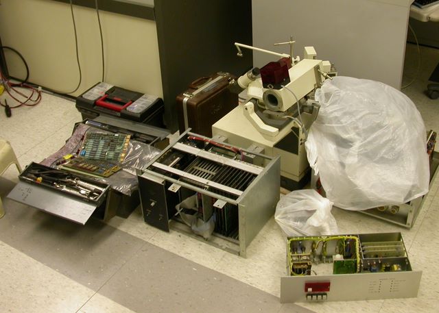
university's old destined-for-garbage Cad 4 bits. This photo shows an
assortment of parts that I got from Northwestern, some of which ended
up going into our Cad 4. The actual goniometer itself, in the upper
right of the picture, is extremely heavy, probably on the order of 400
lbs or so. Scott and I would roll it around the lab on dowels, or else
drag it on carpets, since we could not pick it up. The main bit
missing was the HV tank, a gentle term for what essentially amounts to
a pole transformer in a rectangular box. The repairs made to this
machine includes the following: The HV tank, numerous other repairs to
the x-ray generator, including rebuilding the autotransformer,
replacing some connectors, re-doing the safety circuits, replacing the
x-ray tube itself, rebuilding a flow switch and re-plumbing the
cooling circuits.
The Cad 4 had a PDP-11 inside it to make it work, which is the card cage at the front of the picture. This needing nothing more than a good scrubbing to make it work again. I also had to spend some time with Scott Wilson, the lab's director, rooting around in the optimistically termed 'archives' to find the software for this thing, which originally ran on a VAX. Fortunately, we didn't have to set up the VAX to run this system, as at one point he had paid for the upgrade to PC-based software, and now we had a DOS application to talk to the diffractometer. It took my several months to get this going, including finding spare parts, getting cooling hoses installed, and driving around. While I was doing this I was also a full time student, and designing the rest of this thing as well.
 Step 2: Design the polishing head
This was the last project I did without the aid of CAD
software. I designed this all up in Geoworks, making drawings
using the vector-based drawing package included. I really miss
Geoworks, by the way. It was a wonderfully obvious and easy to
use piece of software. The part I designed is basically
anything shiny aluminum in the photo above. The theory was
that the polishing wheel itself (Brass wheel on the right) was
floating on springs on linear bearings to the drive motor
(black cylinder on right), which could be drive up and down on
its cross member to change the applied force. The up and down
motion was driven by a ball screw by the motor parallel to the
ground, while the oscillating back and forth motion of the
head was driven by the vertical mounted motor.
The School of Chemical Sciences machine shop did all the machining and helped me out a lot with the drawings for this. I needed to learn all about ball screws, worm gears, thrust bearings, motor controls, machining tolerances, and talking to machinists to make this work. The grinding equipment came together quite nicely. I had the benefit of having several other old diffractometers lying around to offer up parts.
 Step 3: Build the control rack
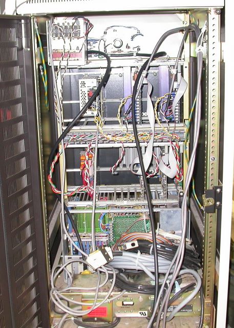
This rack contains the controller for the Cad 4, as well as
the drives for the stepper motors used in the polishing
attachment. The rack came from what was once part of Scott's
VAX 11/750. At top is the DC speed control for the polishing
motor, which was one of the only new things bought for this
project which was not part of the machining. Next down are
two stepper drive card cages, which came from a broken
4-circle diffractometer Scott had in his archives. Next down
is the Cad 4 control cage and its associated wiring. The
bottom of the rack had the original DEC branded power
distribution board, which was nice to have.
 Step 4: Wire the system together
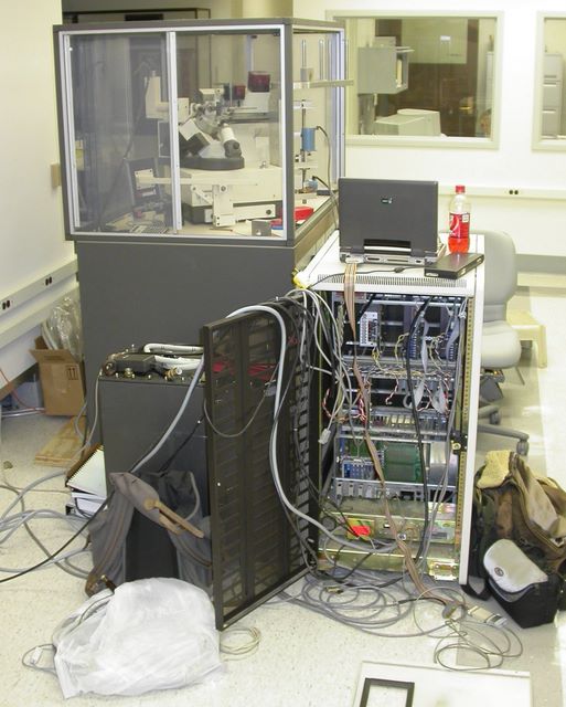
This photo shows the rack where it lived during part of the
development process. That laptop sitting there is another
piece of surplus equipment, on which I did most of the
mechanical design. That 386 and I have a lot of good
memories. Have I mentioned how much I miss Geoworks Ensemble?
The thing ran snappy quick on this 386.
At the left of the rack is the HV tank. Good heavens this thing was heavy. So heavy that it actually would sink into the tile if left in one place for too long. Getting this into the bottom of the Cad 4 was an interesting exercise in simple machines. The HV tank has two eyelets on the top, and we used a combination of 2x4s, metal rods, and little rollers to get it moved into place. Much levity was had rolling this thing around the floor. Helping Scott move heavy, fragile, and potentially very expensive equipment around his lab using ramps and levers is a very positive memory for both my brother and I.
 Step 5: Write some software so the thing actually does something
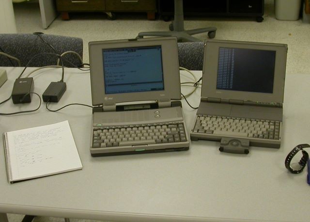
Here are my two vintage laptops. The left is my trusty 386,
and the right was a 486. I'm just using the right hand laptop
as a serial terminal in this photo. The drives for the stepper
motors had an RS-232 port on them, and I needed to write a
simple piece of software to make the motors do their thing in
the proper order. This was a simple GW Basic program I ripped
out in one night, featuring such simple commands as
home, up, down, polish, and stop. When running the
system, the left laptop talks to the stepper controllers, and
the right runs the Cad 4.
 Step 6: Solve other problems not necessarily considered when I set out
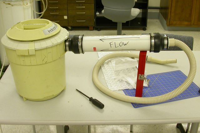
I overlooked dust collection in this. I figured that the
surface I was polishing was going to be so small, who cares?
However, it turns out that whenever you polish something the
edges of the sample get rounded due to how the cut material
gets distributed. To minimize this I chose to encase the
sample in hard transparent epoxy using a mold and a custom
head in the goniostat. This increased the surface area exposed
to the polishing surface, but also created more dust. The
nozzle of the collimeter on the Cad 4 is very small and quite
fragile, and besides, it is not a good idea to have platinum
and epoxy dust blowing around inside your x-ray
equipment. Enter the dust collection system. The vacuum
cleaner came from the physics dock, the same place where
the projector came from. They had a huge pile of
them, presumably at one point used to demonstrate something
cool like hover crafts. Then I got some fine filter material
(think good quality allergen furnace filters), rolled them
into cones, and shoved them into the PVC tube. The dust from
the polishing would be quite fine, and the vacuums were free,
so it made more sense than buying a new shop vac.
 Step 7: See how everything fits.
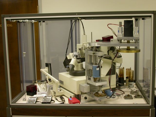
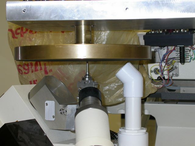
This photo shows the polishing wheel at top, over the
goniometer head with the sample at the tip of the stick. At
right is the dust collection nozzle, and in the foreground is
the microscope used to optically orient the sample. The stick
in the head in this photo is just a piece of metal at the
right height to check the clearances on everything. This
actually worked out quite nicely in making the tip of that
stick shiny. The plastic bag at the back is covering the
collimater and the photomultiplier tube assembly.
 Step 8: See it work
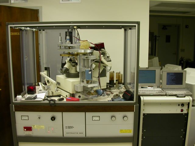
Here's the system largely complete, but before we installed
the X-ray tube. There are spare tubes standing at the right of
the Cad 4's enclosure. The two laptops are at the right, the
control rack is full of it's goodness, and the thing is
actually working. I believe this photo was taken at the same
time as the previous photo was. The next test done on this was
with x-rays that we actually used to orient a sample.
Step 9: Heartbreak
Just as I was moving into final stages of testing with this, I
had to leave for Australia. I made some efforts to find one of
my friends to keep working on this, but that didn't work
out. The sponsor of this project, Dr. Andrzej Wieckowski,
also tried hard to find a grad student to take
over the project, but to no avail. Eventually the lab space
that the Cad 4 was in needed to be used for a new machine, and
this whole machine was scrapped, minus the grinding bits,
which are somewhere around the University of Illinois. The
problems requiring solving when I left were grinding, epoxy
and polishing related. I designed a new counterweight
suspension arm to better control the pressure, and was doing
research into low-friction gas bearings. The epoxy and
polishing related issues I learned a great deal more about
while doing Solar Car stuff in Australia. I returned from
Australia for my super-senior year, and made efforts at
getting back into this project. Unfortunately, the project had
floundered while I was away, and I was unable to complete
it. I did, however, successfully repair the Cad 4, use it to
orient test samples, and polish stainless steel
sticks. Unfortunately, it never did surface platinum for
surface chemistry.

