The RF Tester @ Fermi National Accelerator Lab
I was luckily able to work at Fermi National Accelerator Laboratory for a few summers while studying engineering at U of I. During my summers there, I was working on the NLC project, mostly for Gennady Romanov, a very talented man who was working closely with the design of non superconducting (warm) accelerating structures. The accelerating structures, each on the order of 1 meter long, were comprised of stacks of precision machined disks. These disks were stacked up and bonded together, and then theoretically used to accelerate particles. Producing the disks and the structures were very tricky, involving insane amounts of calculation and truly tiny tolerances.
One of the things I was tasked with was figuring out a better QC system to facilitate testing and sorting. Testing these disks involved placing them between two antenna blocks and then applying a constant load, meant to simulate their behavior in the finished stack. A spectrum analyzer was then used to measure its frequency responses to several different modes important to the nontrivial task of making very tiny things go very very fast. The machine originally used to do this involved a stack of weights on a hinge, and a great big knob on top to apply pressure. This machine was labor intensive to use, and the testing was operator dependent. The amount of force applied was proportional to how hard the operator turned the crank, until the peaks looked about right. This was not repeatable operator-to-operator, so a better solution had to be found.
 The first thought I had, with the goal of repeatable, known pressure was
a pneumatic piston. There was a very nice, clean, filtered air source in the
clean room in which we were operating. I ordered some parts, headed into
the basement, and starting knocking stuff together. This project took nearly
two months, including a week of me cranking through a big book on AutoCad
to learn how to make drawings that the machinists wouldn't laugh at. The
folks in the Technical Divisions' engineering department helped me out a lot
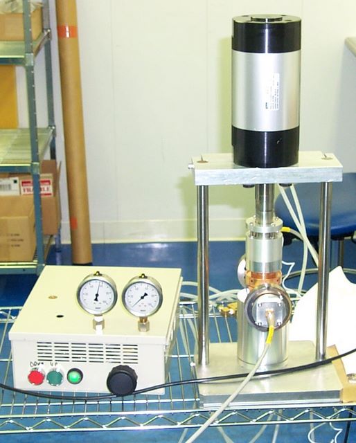
on the mechanics of this. The first revision is shown here, testing the T
joint used to get the power into the structure. The box at left was all
made in the basement, and all the shiny nice metal at right made at the
machine shop at Fermilab's Technical Division. The original idea was that
the air pressure would be good enough to tell the force felt by the disk,
but Gennady wanted a load cell, so I added the load cell. He was right.
It makes it much better. The force of the piston is changed by the
black knob, and the down and up buttons do what you would think. Out the top
are two gages reading pressure in the line and pressure in the cylinder.
The first thought I had, with the goal of repeatable, known pressure was
a pneumatic piston. There was a very nice, clean, filtered air source in the
clean room in which we were operating. I ordered some parts, headed into
the basement, and starting knocking stuff together. This project took nearly
two months, including a week of me cranking through a big book on AutoCad
to learn how to make drawings that the machinists wouldn't laugh at. The
folks in the Technical Divisions' engineering department helped me out a lot
on the mechanics of this. The first revision is shown here, testing the T
joint used to get the power into the structure. The box at left was all
made in the basement, and all the shiny nice metal at right made at the
machine shop at Fermilab's Technical Division. The original idea was that
the air pressure would be good enough to tell the force felt by the disk,
but Gennady wanted a load cell, so I added the load cell. He was right.
It makes it much better. The force of the piston is changed by the
black knob, and the down and up buttons do what you would think. Out the top
are two gages reading pressure in the line and pressure in the cylinder.
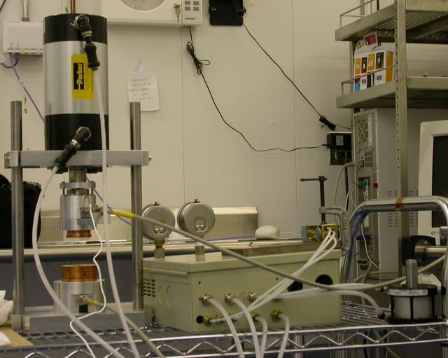 Another view of the first revision, from the back. The original thought involved
a more user-friendly finger/disk interface. The small piston on the far right
was going to be something that slid a little shelf in and out, and the C-clamped
switch on top was going to make the main piston go up and down. This idea failed
due to lack of time. In order to get it done in the time I had, I needed to stop
fooling with CAD models and get the thing built. It was in this configuration that
the research group used this machine for the better part of a year, testing all
the disks and couplers that came through the lab.
Another view of the first revision, from the back. The original thought involved
a more user-friendly finger/disk interface. The small piston on the far right
was going to be something that slid a little shelf in and out, and the C-clamped
switch on top was going to make the main piston go up and down. This idea failed
due to lack of time. In order to get it done in the time I had, I needed to stop
fooling with CAD models and get the thing built. It was in this configuration that
the research group used this machine for the better part of a year, testing all
the disks and couplers that came through the lab.
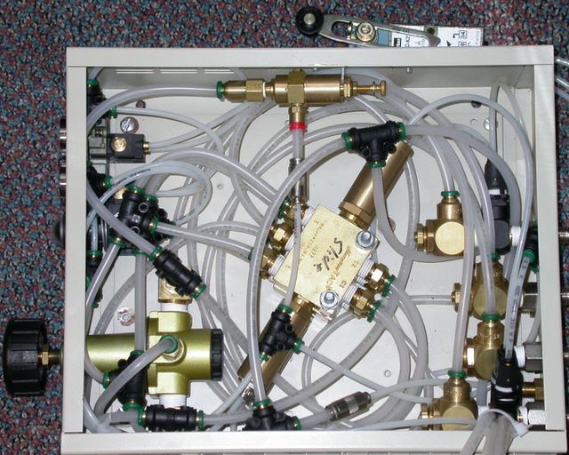 The downside of this device was the heinously small box and overzealous use of tiny
tubes. This was my first project using pneumatics, and I got a little ahead of
myself, creating a pipe leak center that only 1970's engine designers could have beat.
In the center are the two valves that operated the up-and-down piston and what was
supposed to be the slide in-and-out piston. At right are the flow restrictors to
keep the pistons from slamming up and down too quickly. At the top is the control
pressure regulator, which regulated the line air down to a pressure for the pushbuttons
and air sensors. At the lower left is the main regulator, which was a piece of equipment
from my father's stock of air tools in the basement. The bundle of hoses to the valve and
the main on/off switch is seen at the lower right. This mess of tubes, a classic example
of 10 pounds of crap in a 5 pound bag, did exactly what it should, to the annoyance of
the people who used it- Since it was designed to operate two pistons, the operator
needed to push the green button on the front, then push the little detector switch
at the top, which would cause the pressure piston to go down.
The downside of this device was the heinously small box and overzealous use of tiny
tubes. This was my first project using pneumatics, and I got a little ahead of
myself, creating a pipe leak center that only 1970's engine designers could have beat.
In the center are the two valves that operated the up-and-down piston and what was
supposed to be the slide in-and-out piston. At right are the flow restrictors to
keep the pistons from slamming up and down too quickly. At the top is the control
pressure regulator, which regulated the line air down to a pressure for the pushbuttons
and air sensors. At the lower left is the main regulator, which was a piece of equipment
from my father's stock of air tools in the basement. The bundle of hoses to the valve and
the main on/off switch is seen at the lower right. This mess of tubes, a classic example
of 10 pounds of crap in a 5 pound bag, did exactly what it should, to the annoyance of
the people who used it- Since it was designed to operate two pistons, the operator
needed to push the green button on the front, then push the little detector switch
at the top, which would cause the pressure piston to go down.
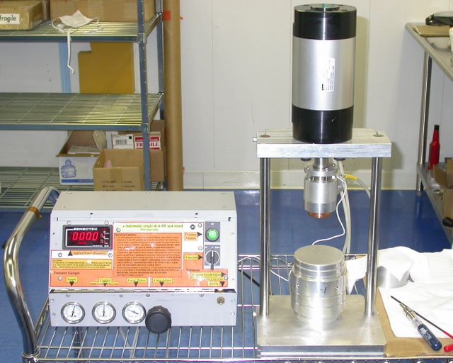 The following summer I came back again, this time with some more sense about me.
I was impressed that Gennady and the folks at this part of the NLC group were using
the thing, and they decided they liked it and wanted a better, more robust, and
less messy version. The metal bits on the right are mainly the same- They built
more antenna blocks and adapters to test different kinds of things, but the overall
function remained the same. First thing I did was throw out the stuff that did not
work on the previous version. This included the extra slide feature, which was
deemed not worth the effort. The control box now features the Sensotec load cell
readout on board, and a simple one-handed back and forth knob to control the
operation of the force applier. There are also instructions printed on a nice
laminated sheet, riveted on to the front of the chassis. The gages across the front
read incoming line, control, and cylinder pressures. The big black knob still sets
the applied force. There is that tiny switch on the right, which is the main air
on/off switch. The green indicator tells that operator that the system is pressurized,
and the black knob makes the cylinder go up and down. The system was typically set to
apply around 300 lbs of pressure to the disks under test. Using the lab air supply,
the system operated effectively from 50 lbs up to about 500 lbs, at which point
the aluminum cross at the top would start deflecting alarmingly.
The following summer I came back again, this time with some more sense about me.
I was impressed that Gennady and the folks at this part of the NLC group were using
the thing, and they decided they liked it and wanted a better, more robust, and
less messy version. The metal bits on the right are mainly the same- They built
more antenna blocks and adapters to test different kinds of things, but the overall
function remained the same. First thing I did was throw out the stuff that did not
work on the previous version. This included the extra slide feature, which was
deemed not worth the effort. The control box now features the Sensotec load cell
readout on board, and a simple one-handed back and forth knob to control the
operation of the force applier. There are also instructions printed on a nice
laminated sheet, riveted on to the front of the chassis. The gages across the front
read incoming line, control, and cylinder pressures. The big black knob still sets
the applied force. There is that tiny switch on the right, which is the main air
on/off switch. The green indicator tells that operator that the system is pressurized,
and the black knob makes the cylinder go up and down. The system was typically set to
apply around 300 lbs of pressure to the disks under test. Using the lab air supply,
the system operated effectively from 50 lbs up to about 500 lbs, at which point
the aluminum cross at the top would start deflecting alarmingly.
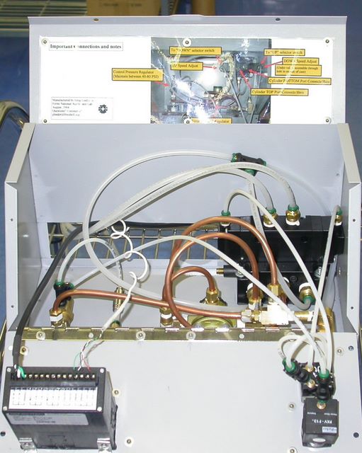 This is what the box looks like inside. I decided to user copper for tubing that did
not need to leave the box. This not only makes the thing look cooler, but it also helps
to minimize tubing clutter. There is also a new valve block in here. Rather than using
the valves in the previous version, I chose to use a bussed device with internal flow
restriction. This was done as a measure of making things look better and be more stable
and less leak-prone. The other valving solution had more air connections and threaded
bits. The valve block is the black unit at the right side of the picture. The flow
restriction adjustment screws can be seen sticking out to the lower left and lower
right on the valve block. The right hand adjustment screw is accessed via a hole in
the side of the case. The main air line regulator is seen with the two large swooping
copper tubes. The control switch and indicator is at the lower right, with the back
of the Sensotec readout at the lower left. Because I knew that I would most likely
never be back to repair this thing, I riveted a color photo with all the parts
labeled inside the top cover.
This is what the box looks like inside. I decided to user copper for tubing that did
not need to leave the box. This not only makes the thing look cooler, but it also helps
to minimize tubing clutter. There is also a new valve block in here. Rather than using
the valves in the previous version, I chose to use a bussed device with internal flow
restriction. This was done as a measure of making things look better and be more stable
and less leak-prone. The other valving solution had more air connections and threaded
bits. The valve block is the black unit at the right side of the picture. The flow
restriction adjustment screws can be seen sticking out to the lower left and lower
right on the valve block. The right hand adjustment screw is accessed via a hole in
the side of the case. The main air line regulator is seen with the two large swooping
copper tubes. The control switch and indicator is at the lower right, with the back
of the Sensotec readout at the lower left. Because I knew that I would most likely
never be back to repair this thing, I riveted a color photo with all the parts
labeled inside the top cover.
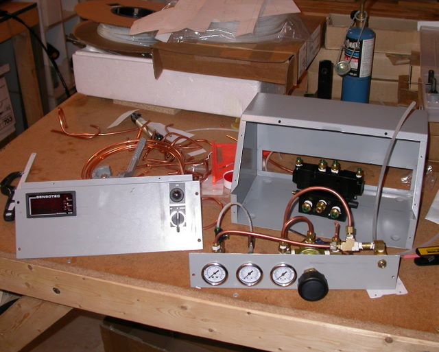 Here's what the parts looked like on the bench in the basement of the Linder House.
Originally, the front of this box was one piece that screwed on. I needed to make
it hinged so I could have the top fold open, as shown in the previous picture.
This took a lot of hack-sawing and filing, but I think the results are quite
practical and useful. Once the unit is put together, all the hoses and fittings
can be got at without taking the front of the thing apart. This was the first
project I did using a chassis punch (or "slug buster"), which I now acknowledge as
one of the best innovations in the universe. Also the first for worrying about
copper line for pressurized air. After I left Fermilab, this rig
was used to measure superconducting structures, as the NLC steering committee
decided that the "high temp" solution (copper) was not the way they were going to go.
I should see if they are still using this equipment.
Here's what the parts looked like on the bench in the basement of the Linder House.
Originally, the front of this box was one piece that screwed on. I needed to make
it hinged so I could have the top fold open, as shown in the previous picture.
This took a lot of hack-sawing and filing, but I think the results are quite
practical and useful. Once the unit is put together, all the hoses and fittings
can be got at without taking the front of the thing apart. This was the first
project I did using a chassis punch (or "slug buster"), which I now acknowledge as
one of the best innovations in the universe. Also the first for worrying about
copper line for pressurized air. After I left Fermilab, this rig
was used to measure superconducting structures, as the NLC steering committee
decided that the "high temp" solution (copper) was not the way they were going to go.
I should see if they are still using this equipment.

