The Hotbox @ SmartSpark Energy Systems
![]() For those of you crazy enough to want to look through it, the
PIC18F assembly for
the hotbox is available by clicking on the icon to the left.
For those of you crazy enough to want to look through it, the
PIC18F assembly for
the hotbox is available by clicking on the icon to the left.
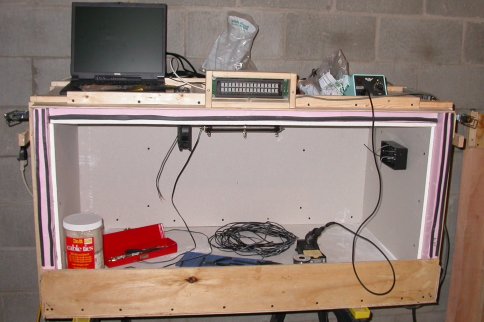 While still a student, I was moonlighting at SmartSpark. They told me that
they needed to do some environmental testing on batteries, to heat them
up to test the robustness of the batteries and characterize how they age.
The result was my invention of the first HotBox. SmartSpark now has a couple
of them, now built
by different people. In a nutshell, this is an insulated box with a thermostat
capable of keeping the temperature within 1-2 deg C of a programmable setpoint,
a resistor for heat, and some
fans for mixing. The box itself is lined with drywall on the inside, primarily
as a fire-proofing measure. Pink Foam is relatively flammable, and batteries
under heavy use conditions have been known to explode. The inside dimensions
are about 2' deep, 2' high, and 4' wide.
While still a student, I was moonlighting at SmartSpark. They told me that
they needed to do some environmental testing on batteries, to heat them
up to test the robustness of the batteries and characterize how they age.
The result was my invention of the first HotBox. SmartSpark now has a couple
of them, now built
by different people. In a nutshell, this is an insulated box with a thermostat
capable of keeping the temperature within 1-2 deg C of a programmable setpoint,
a resistor for heat, and some
fans for mixing. The box itself is lined with drywall on the inside, primarily
as a fire-proofing measure. Pink Foam is relatively flammable, and batteries
under heavy use conditions have been known to explode. The inside dimensions
are about 2' deep, 2' high, and 4' wide.
As pictured, there is only one resistor. The "production" verson has
two resistors, a coarse and a fine: one for heating up from ambient, and
another for regulating around the setpoint. The design max operating temp was 65C,
and there is a thermal link in the AC heater wiring that opens up at 85C.
 In typical "Linderizing style", I decided to roll my own controller. Future
versions used off the shelf digital temp controls ordered from Grainger,
but I was looking to do something geeky. The controller uses a PIC18F (slightly
overkill, but I had leftovers from the FEC motor drive project), and features
two independent temperature channels in, three relays out (heater 1 and 2, fan), a
single knob to scroll through menus with a push-to-select, and a keyswitch
to lock out the settings. The menus are displayed on a 2 line serial interface
VFD (think cash register display). All the code was done with Microchip's IDE
in assembly.
In typical "Linderizing style", I decided to roll my own controller. Future
versions used off the shelf digital temp controls ordered from Grainger,
but I was looking to do something geeky. The controller uses a PIC18F (slightly
overkill, but I had leftovers from the FEC motor drive project), and features
two independent temperature channels in, three relays out (heater 1 and 2, fan), a
single knob to scroll through menus with a push-to-select, and a keyswitch
to lock out the settings. The menus are displayed on a 2 line serial interface
VFD (think cash register display). All the code was done with Microchip's IDE
in assembly.
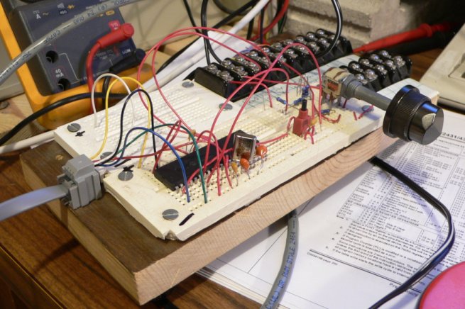 This is the prototype control board, the circuit eventually installed in the
control box above.
As most of my through-hole projects begin, this started on that ubiquitous
white plugboard. A while ago I glued some hunks of this onto a block of wood
and added screw terminals since it makes things a bit more "road rugged" when
running a transient EE design shop. The prototype looks as I feel most prototypes
do: Wires hanging out and developed on a messy desk.
The rotary encoder is a surplus radio knob from a piece of garage sale junk
dismantled sometime in my distant youth. I find that it is very handy to have
an assortment of parts pertaining to the current project. I've managed to accrue
a couple of parts boxes that hold common widgets (standoffs, switches, sockets,
resistors) that come in handy if I am scratching my head going "What would be
a cool way to solve this problem?"
At this point, when I start a project, I keep all the parts for the project in
a plastic box that travels with the project. This makes finding spare parts very
easy.
This is the prototype control board, the circuit eventually installed in the
control box above.
As most of my through-hole projects begin, this started on that ubiquitous
white plugboard. A while ago I glued some hunks of this onto a block of wood
and added screw terminals since it makes things a bit more "road rugged" when
running a transient EE design shop. The prototype looks as I feel most prototypes
do: Wires hanging out and developed on a messy desk.
The rotary encoder is a surplus radio knob from a piece of garage sale junk
dismantled sometime in my distant youth. I find that it is very handy to have
an assortment of parts pertaining to the current project. I've managed to accrue
a couple of parts boxes that hold common widgets (standoffs, switches, sockets,
resistors) that come in handy if I am scratching my head going "What would be
a cool way to solve this problem?"
At this point, when I start a project, I keep all the parts for the project in
a plastic box that travels with the project. This makes finding spare parts very
easy.
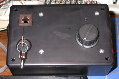
 To the left is the version of the hotbox controller that actually
"shipped" and is in use. The plastic shaft protruding is the rotary encoder. I've
gotten pretty good at lining up holes on plastic boxes to fit reset buttons
and the like on hand-soldered boards. The control board is enclosed in a box
that hangs off a long wire away from the hotbox itself. The thinking on this
feature was that the box would be relatively inaccessible hence requiring
a long wire to the controls. It turns out this was not the case.
To the left is the version of the hotbox controller that actually
"shipped" and is in use. The plastic shaft protruding is the rotary encoder. I've
gotten pretty good at lining up holes on plastic boxes to fit reset buttons
and the like on hand-soldered boards. The control board is enclosed in a box
that hangs off a long wire away from the hotbox itself. The thinking on this
feature was that the box would be relatively inaccessible hence requiring
a long wire to the controls. It turns out this was not the case.
I think this might be the last hand-soldered board
I will make. PCB fabbing has come down in cost, and I have been using more and
more surface mount components in my designs. Also, the amount of pleasure I derive from
bending tiny wires and all that is beginning to wain. I'm pretty good at it,
and the skills from fabbing boards like this make my hands very dexterous at doing tiny PCB
work.
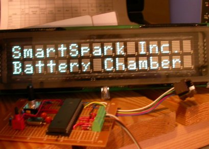 Here's what the thing looks like when it is running- The VFD took some tweaking
to get it going, since it came out of a $1 box at a hamfest. But it's really bright,
and kind of fun. When not using the menus with the wheel, the bottom line scrolls
the system status scrolling-sign style. I've had a certain affection for
scrolling signs since the ACM internet-connected scrolling sign caught my fancy when
I was younger. I never took a photo of the menus. Pushing the wheel in brings
it to config mode, and rotating the wheel selects the option to change. In
my quest to make things obvious to the end user one knob and a display
seems easier than multiple buttons. It also looks cooler.
Here's what the thing looks like when it is running- The VFD took some tweaking
to get it going, since it came out of a $1 box at a hamfest. But it's really bright,
and kind of fun. When not using the menus with the wheel, the bottom line scrolls
the system status scrolling-sign style. I've had a certain affection for
scrolling signs since the ACM internet-connected scrolling sign caught my fancy when
I was younger. I never took a photo of the menus. Pushing the wheel in brings
it to config mode, and rotating the wheel selects the option to change. In
my quest to make things obvious to the end user one knob and a display
seems easier than multiple buttons. It also looks cooler.
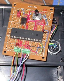
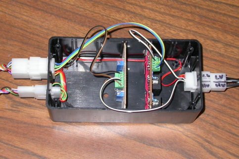 The last picture here is the interface box. The wires out the left goes
to the VFD and the control box, the wires out the right to the power supply
(another one of those great junk-box finds). The holes in the back of this
box are feed throughs for a wiring box on the inside of the hotbox. It turns out
that the typical radio shack plastic boxes start to deform at like 70C, as I found
during testing. Oops.
The last picture here is the interface box. The wires out the left goes
to the VFD and the control box, the wires out the right to the power supply
(another one of those great junk-box finds). The holes in the back of this
box are feed throughs for a wiring box on the inside of the hotbox. It turns out
that the typical radio shack plastic boxes start to deform at like 70C, as I found
during testing. Oops.
The boards are the relay and opamp PCB. In retrospect, I should have used a
better temp sensor that didn't need it (why add more chips?).
The relay PCB just has drive transistors, diodes
and 120V relays for the heaters and fan.

