Poop Digester Version 2: Introduction
The first semester digester project, presented
here ended
in December, 2008. The research group needed a fully-featured manure
digester to get their work done, and I needed to make headway in
my research as well.
This digester combines knowledge from the previous semester in manure digester
design, coupled with site visits to a couple of state-of-the-art digester
facilities in the North Country. The result, after about eight weeks of work,
is the Clarkson Anaerobic Manure Digester. This machine is a fully equipped
digester. The only original parts left from the previous semester that
weren't removed, cleaned, re-attached and re-designed was the tank itself.
The trailer even got a new set of wheels. Nearly all of the construction
work and most of the engineering was done by myself, Shaun Jones, and Dan Valyu.
There's a photo of the three of us later in the document. Thanks to the
Biomass Group and the great shop staff at Clarkson who were helpful and
available, and taught me how to weld.
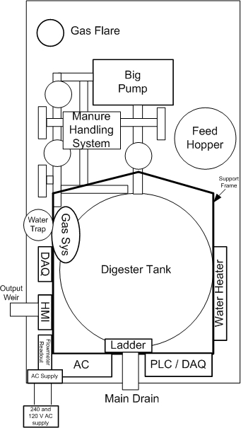 The component layout of the new digester is shown at right, looking top down
in schematic form. At time of writing, in June, 2008, the system is up and
running, taking data for the summer research at Clarkson. For further
information, feel free to download the digester's
instruction manual
The manure handling system is all 3 inch schedule 80 PVC or galvanized steel.
All joints that may need to be removed are bolt flanges, The pump is installed with
bypass throttling and a pump reverser, to enable us to mix the tank backwards
if we need to remove sediment. Thanks to Dan for that suggestion.
The manure system is equipped with lots of extra valves, to enable us plumb
the recirculating pump to various external systems. The system is also equipped
with an ultrasonic flow meter on the manure plumbing.
The water heater system has been redesigned. Originally a tank-based system with
bang-bang control, it was replaced with a dual-control loop flow through design.
One loop controls the tank temperature, and the other controls water temperature.
The water pump was also replaced with a pump more suited to the job of circulating
heating fluid. This saved us energy, and enabled a reliable, repeatable flow rate
(16 GPM).
The tank also has a support frame around it. The frame supports the electronics
enclosures, water heating system, gas system, and conduit and wire.
The frame makes it much easier to work on and install things, compared to the previous
way of attaching things to the lid.
The component layout of the new digester is shown at right, looking top down
in schematic form. At time of writing, in June, 2008, the system is up and
running, taking data for the summer research at Clarkson. For further
information, feel free to download the digester's
instruction manual
The manure handling system is all 3 inch schedule 80 PVC or galvanized steel.
All joints that may need to be removed are bolt flanges, The pump is installed with
bypass throttling and a pump reverser, to enable us to mix the tank backwards
if we need to remove sediment. Thanks to Dan for that suggestion.
The manure system is equipped with lots of extra valves, to enable us plumb
the recirculating pump to various external systems. The system is also equipped
with an ultrasonic flow meter on the manure plumbing.
The water heater system has been redesigned. Originally a tank-based system with
bang-bang control, it was replaced with a dual-control loop flow through design.
One loop controls the tank temperature, and the other controls water temperature.
The water pump was also replaced with a pump more suited to the job of circulating
heating fluid. This saved us energy, and enabled a reliable, repeatable flow rate
(16 GPM).
The tank also has a support frame around it. The frame supports the electronics
enclosures, water heating system, gas system, and conduit and wire.
The frame makes it much easier to work on and install things, compared to the previous
way of attaching things to the lid.
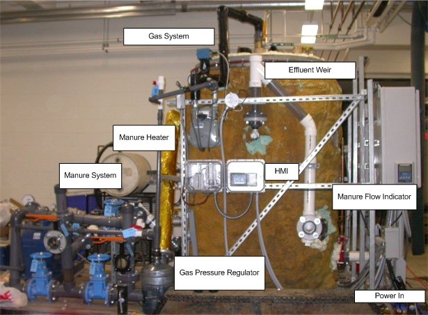 A view of the digester in the shop at Clarkson, showing the system from the side.
All key parts are labeled. At the right is the circuit breaker panel and the manure
ultrasonic flow meter. The bolt flange immediately to the right is the effluent
output. The top of that pipe is transparent to the weir itself, which has an
open top to prevent siphoning the tank when the system is drains. The tank pressure
was set to be around 9 inches of water when full.
A view of the digester in the shop at Clarkson, showing the system from the side.
All key parts are labeled. At the right is the circuit breaker panel and the manure
ultrasonic flow meter. The bolt flange immediately to the right is the effluent
output. The top of that pipe is transparent to the weir itself, which has an
open top to prevent siphoning the tank when the system is drains. The tank pressure
was set to be around 9 inches of water when full.
Continue going to the left,
the gas system meter and pipe is at the top, all continuously heated to keep water
vapor from condensing out of the gas. The HMI LCD panel is also visible, and a
side view of the manure system. Each of those big blue valves is around 60 lbs.
There is a section of pipe wrapped in gold material. That is the manure
inlet heater, designed to compensate the tank temperature for the inclusion of a
slug of cool manure when being fed. The tank holds around 515 gallons total,
of which 45 is in all the pipes and plumbing.
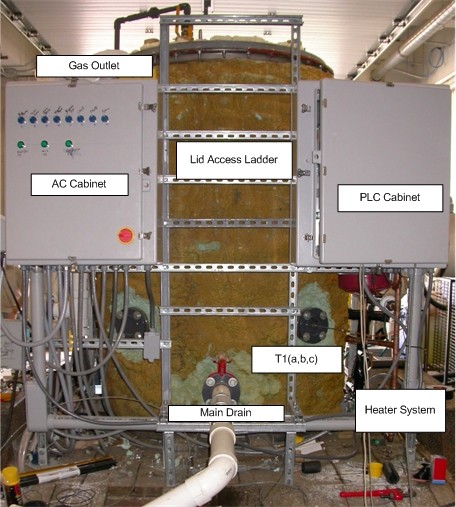 The back view of the digester. Left is the AC cabinet, containing contactors,
overloads, and AC distribution. Right hand is the PLC cabinet, with contains the
SixNet hardware and DC power supply. Up the center is the access ladder, which
was absolutely wonderful to have when welding inside the tank. The main
drain is visible at the bottom of the frame, with a 3 inch pipe coming
out of it. At the far right of the frame is some of the copper of the heating
system.
The back view of the digester. Left is the AC cabinet, containing contactors,
overloads, and AC distribution. Right hand is the PLC cabinet, with contains the
SixNet hardware and DC power supply. Up the center is the access ladder, which
was absolutely wonderful to have when welding inside the tank. The main
drain is visible at the bottom of the frame, with a 3 inch pipe coming
out of it. At the far right of the frame is some of the copper of the heating
system.
As with the previous digester, all the electrical equipment is mounted in NEMA 4X
or 3R enclosures, where applicable. All cables are pulled in Sealtite or other
weatherproof fittings, and AC and DC equipment are separated in different
enclosures, to preserve the signal integrity of the DAQ channels,
and make data downloading and PLC maintenance safer.
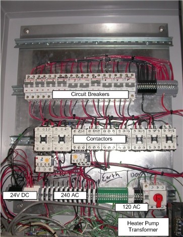 Inside the left hand enclosure, showing the circuit breakers, contactors,
and associated hardware. At left is the 24V DC distribution, next to the 240V AC.
I would rather have not done it this way, but due to time and money I was re-using
a lot of the old conduit and enclosures from the previous version of the digester,
and it just happened that the 24 V DC all wanted to come together here. At the
lower right is the transformer for the heater pump.
Due to time constraints, a 240 V heater pump could not be located in time,
so a 120V pump with a step down transformer was used instead. We are
till operating safely within the pump's rating. Only four of the
contactors are currently used, from left to right, the big manure
pump, the heater element, the heater pump, and the manure heater.
The rest of the contactors are for the future systems to be
integrated with the digester's controller.
Inside the left hand enclosure, showing the circuit breakers, contactors,
and associated hardware. At left is the 24V DC distribution, next to the 240V AC.
I would rather have not done it this way, but due to time and money I was re-using
a lot of the old conduit and enclosures from the previous version of the digester,
and it just happened that the 24 V DC all wanted to come together here. At the
lower right is the transformer for the heater pump.
Due to time constraints, a 240 V heater pump could not be located in time,
so a 120V pump with a step down transformer was used instead. We are
till operating safely within the pump's rating. Only four of the
contactors are currently used, from left to right, the big manure
pump, the heater element, the heater pump, and the manure heater.
The rest of the contactors are for the future systems to be
integrated with the digester's controller.
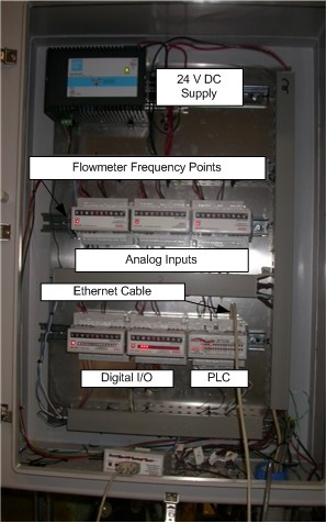 This is a photo of the PLC enclosure. This cabinet contains the 24V power
supply for all the low voltage hardware, much of the analog input hardware,
and all the digital IO and the PLC itself.
There is another set of A/D modules mounted next to the HMI, to save
thermocouple wire pulling headaches. SixNet was very nice about
giving us a good deal on this hardware, and it has been a pleasure to work with.
This is a photo of the PLC enclosure. This cabinet contains the 24V power
supply for all the low voltage hardware, much of the analog input hardware,
and all the digital IO and the PLC itself.
There is another set of A/D modules mounted next to the HMI, to save
thermocouple wire pulling headaches. SixNet was very nice about
giving us a good deal on this hardware, and it has been a pleasure to work with.
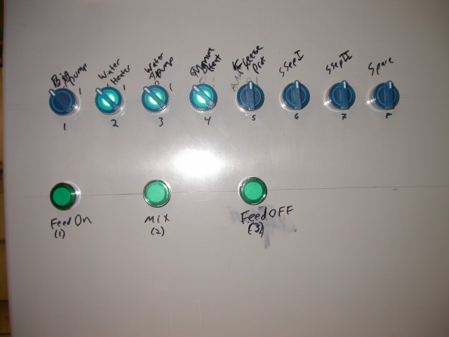 This is a photo of the control panel itself. These controls are located on the
front of the AC panel, even though most of the wires run back to the DC panel.
Once again, this is due to the re-use of hardware from the previous digester.
The top row of knobs are wired for auto/off/on type operation. The bottom
row of pushbuttons are for semi-automatic operation. This allows us to have
asynchronous feeding times at user discretion, while still running the pumps
and other systems in a controlled manner. One of tricks of this was to keep
the current down for use on a 30 A 240V farm electrical service.
These pushbuttons enable that to happen.
This is a photo of the control panel itself. These controls are located on the
front of the AC panel, even though most of the wires run back to the DC panel.
Once again, this is due to the re-use of hardware from the previous digester.
The top row of knobs are wired for auto/off/on type operation. The bottom
row of pushbuttons are for semi-automatic operation. This allows us to have
asynchronous feeding times at user discretion, while still running the pumps
and other systems in a controlled manner. One of tricks of this was to keep
the current down for use on a 30 A 240V farm electrical service.
These pushbuttons enable that to happen.
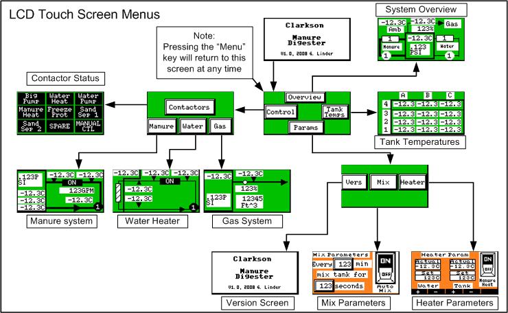 This is a view of the screens available on the HMI. I wanted to make it as easy as
possible to configure digester options and see the real time data. The
DAQ system takes a sample of all parameters every 10 minutes, but I wanted a
way for the operators to tell what was happening in real time. The screens are
divided to enable monitoring of the manure, water, and gas systems, and set the
mix and heat parameters. You can also view the tank temperatures in real time.
A high level screen showing key digester health parameters is available in the
overview button.
This is a view of the screens available on the HMI. I wanted to make it as easy as
possible to configure digester options and see the real time data. The
DAQ system takes a sample of all parameters every 10 minutes, but I wanted a
way for the operators to tell what was happening in real time. The screens are
divided to enable monitoring of the manure, water, and gas systems, and set the
mix and heat parameters. You can also view the tank temperatures in real time.
A high level screen showing key digester health parameters is available in the
overview button.

