Digester Version 2: More on the electrical system
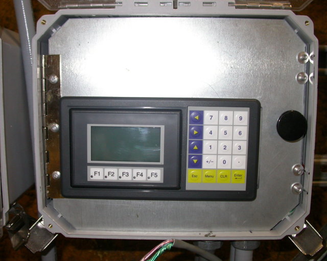 This is a view of the HMI panel used on the new digester.
It is a fairly inexpensive piece of hardware, and offers a
touch screen LCD display and a membrane keypad. When
the digester is in operation, this LCD shows all the
operating parameters and logged data channels. Numeric
entry is possible on the keypad for temperatures
and runnign times.
This is a view of the HMI panel used on the new digester.
It is a fairly inexpensive piece of hardware, and offers a
touch screen LCD display and a membrane keypad. When
the digester is in operation, this LCD shows all the
operating parameters and logged data channels. Numeric
entry is possible on the keypad for temperatures
and runnign times.
Mounting this panel took me a very long time.
Ordinarily, this type of stuff would be mounted on the
front of a cabinet, and it comes with a nice cardboard
outline that you just trace onto the panel and cut. However,
for the digester, the panel had to be rated for
outside exposure. This means I had to install it inside a box.
Furthermore, I had to be able to get at the wiring inside,
as several communications lines pass through this
box on their way someplace else.
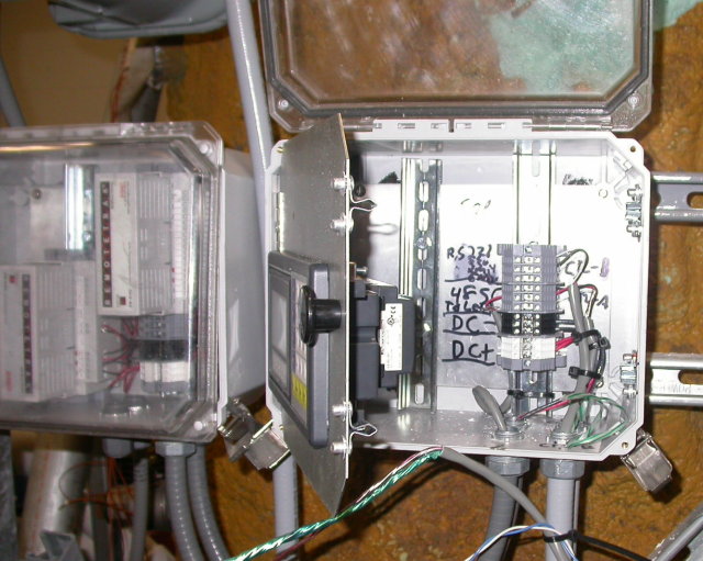 The answer was mounting the HMI on a hinged section that
can be swung out of the way to get at the wires inside.
This photo shows the control panel, swung open,
revealing the wires underneath. When shut, the box is NEMA-4X,
but when open it allows complete access for wiring and HMI
configuration. I chose transparent front boxes for this
equipment so that the operator can see the system
overview screen without opening up the box.
This control panel is located near the valves and
the effluent line, the intent being to mount it nearest
all the action. To the left of this is another
thermocouple input panel, which talks over RS-485
back to the main PLC cabinet.
The answer was mounting the HMI on a hinged section that
can be swung out of the way to get at the wires inside.
This photo shows the control panel, swung open,
revealing the wires underneath. When shut, the box is NEMA-4X,
but when open it allows complete access for wiring and HMI
configuration. I chose transparent front boxes for this
equipment so that the operator can see the system
overview screen without opening up the box.
This control panel is located near the valves and
the effluent line, the intent being to mount it nearest
all the action. To the left of this is another
thermocouple input panel, which talks over RS-485
back to the main PLC cabinet.
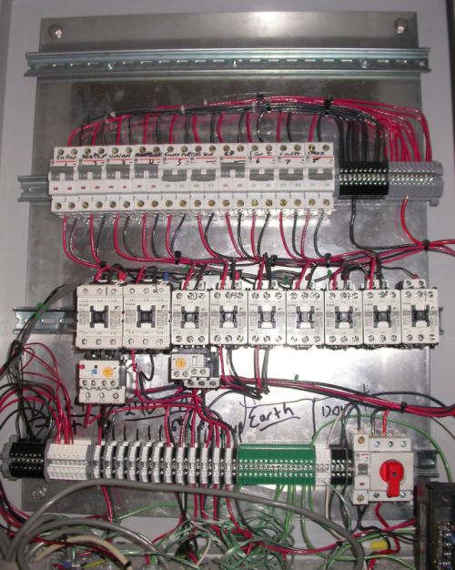 Here is an unlabeled, close up view of the AC enclosure.
Circuit breakers on top, contactors in the center, wire distribution
out the bottom. Lower right hand side is the main switch,
120V aux outlet breaker, and pump motor transformer.
Due to design constraints, the 24V DC is in the lower left hand
corner, immediately adjacent to the 240V AC terminal strips.
Here is an unlabeled, close up view of the AC enclosure.
Circuit breakers on top, contactors in the center, wire distribution
out the bottom. Lower right hand side is the main switch,
120V aux outlet breaker, and pump motor transformer.
Due to design constraints, the 24V DC is in the lower left hand
corner, immediately adjacent to the 240V AC terminal strips.
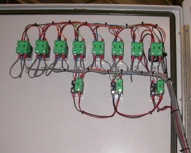 There is something really nice about good rows of happily
organized and zip-tied wires. This photo shows the back
of the AC control panel. At the bottom are the illuminated
pushbuttons used to feed and mix the tank, and the
top are the auto/off/manual switches for the pump contactors.
There is something really nice about good rows of happily
organized and zip-tied wires. This photo shows the back
of the AC control panel. At the bottom are the illuminated
pushbuttons used to feed and mix the tank, and the
top are the auto/off/manual switches for the pump contactors.
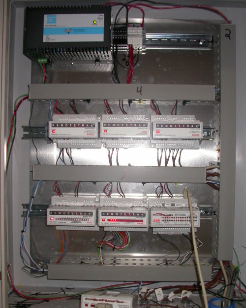 Here is another view inside the PLC enclosure. It appears to be
a lot of hardware, but it is tough to meet specifications
when they are always changing.
Here is another view inside the PLC enclosure. It appears to be
a lot of hardware, but it is tough to meet specifications
when they are always changing.

