The Anaerobic Digester, an introduction
After entering into my mid 20's crisis, and feeling that I needed to learn more stuff, I chose to go back to school. This time, for a master's degree in Electrical Engineering. In particular, my research revolves around SCADA systems for small scale grid interactive power generating equipment. It so happened that Clarkson University had a research digester that needed a SCADA system. Clarkson also offered to foot the bill, which helped seal the deal.
It turns out, however, that the digester needed quite a lot more work than I initially thought. As such, I ended up designing a gas system, manure pump controllers, and a full electrical panel, among other things, before I could get to the actual SCADA end of things. As a result of this, the very nice PLC/RTU I purchased from SixNet was only used as a data acquisition node in the first deployment, a role it fulfilled very well. The digester is back in the shop for the winter, being re-manufactured for deployment again in spring, this time (hopefully) under fully automatic SCADA-enabled control.
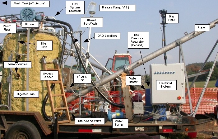
Above is a photo of the digester as it was initially deployed, in case the reader is curious to see where various parts lie with regards to the actual system. The knobs on the electrical panel, for scale, are about chin high on me (I am 6'3"). The tank has an operating volume of 400 gallons, and runs at a pressure of 8 3/8 inches of water. When we were operating successfully, the gas output was between 25-30 cubic feet per day at nearly 60% methane by volume, which are apparently pretty standard numbers for this scale of equipment. The large diagonal member protruding from the tank bottom is an auger, which is part of an experimental sand separation system.
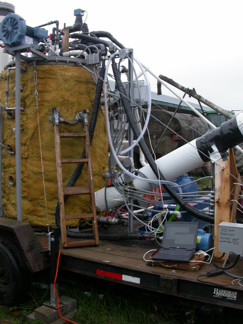 Here is another photo, closer up, showing the conduit that I installed to run the pumps and equipment. The auger is now insulated and heater taped, and my poor Dell Latitude (also seen on the FEC pages here) is busy talking to the PLC so we can see the real time temperature data. All the wiring and electrical equipment is as close to NEMA 4X as I could get, given that the entire system is exposed to the weather. I would have preferred thicker electrical conduit, rather than all the small runs of 3/8" and 1/2" Sealtite, but due to the relatively fluid nature of the design, this ended up working out quite well. Visible at right in the frame is the 240V breaker. The available electrical supply had no neutral, so the system has two breakers. One 240 V located here, which ran all the digester's equipment, and another 120V breaker, located in the barn, was terminated only at a couple of outlets on the digester to run power tools, temporary pumps, and laptops.
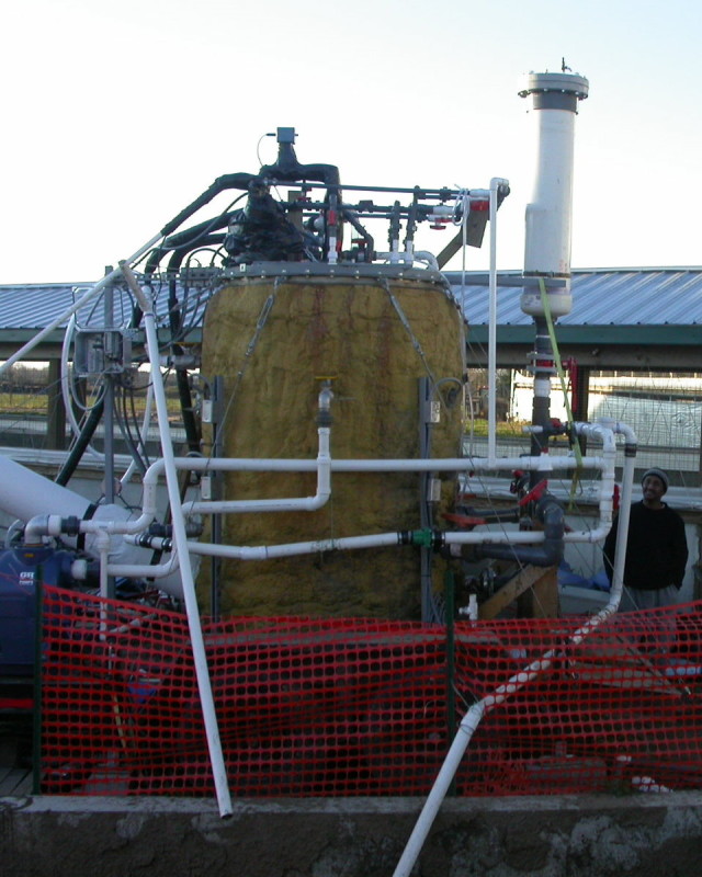 Here is the other side of the tank, with the manure lagoon visible in the lower foreground. Yotam is standing just behind the 2. inlet feed line, for scale. The initial plumbing design was quite a lot more elegant than this, but due to problems we had with the sand separation system, and pumping in general, we kept adding more pipes and fittings to get around the incredibly viscous and variable nature of sand-laden dairy manure. The large white tank at right was initially part of another sand separation technology, which eventually was turned into a substitute manure pump using vacuum instead of rotating parts. The large pump at left was also for the sand removal system. Tank pressure was controlled through two means. The pipe going into the lagoon on the left side of the frame is connected to a weir set at the proper tank pressure. The gas system also has a back pressure regulator to keep air out of the tank. Visible at the top of the frame is part of the gas measurement system. It is all wrapped in black plastic and heater taped to keep the gas at constant temperature through its various measurement instruments.
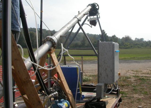 A view up the auger, in its uninsulated form. The NEMA 4X electrical enclosure is seen at the right of the frame. This box contains contactors, a thermostat, and extra space where the PLC interconnection terminations were supposed to be installed. Underneath the blue garbage can is part of the water heater system, and visible in the back left is the gas flare.
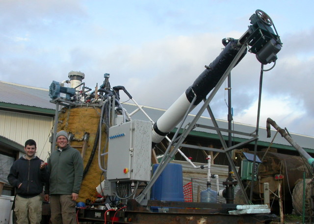 Guillaume and myself, posing in front of the digester. He is a smart and hands-on engineer who characterized the flow properties of water/sand and effluent/sand flows, through a series of experiments immortalized by the phrase .bucket experiments.. These experiments basically involved standing outside in the cold for several hours, pouring manure from a drain back into the bucket it had just come out of, until steady-state conditions would permit measurements of slope angle and flow characteristics. He and I worked together on several versions of "Guillaume's Pump". He was also responsible for many innovations in other areas of digester design, and is a fun and friendly guy to boot. Guillaume is officially a fellow "Big Baller" on account of some of his more dirty and selfless contributions to the project.

