The Anaerobic Digester Electrical System
When I arrived at Clarkson, the entirety of the "electrical system" for the digester consisted of an extension cord into which things were plugged. This was not functional for field deployment, nor was it possible to automate this for control via a PLC. The first thing to do was to design and build a cabinet full of motor starters, contactors, and circuit breakers for the equipment to be installed. Originally, the pump motors and heater were specified for 120 V, which would have required something like 50 Amps @ 120 V, which is not available in any standard household outlet. It turns out that the farm had 240V @ 30 A available immediately near the digester, so we converted all the equipment to 240, and I ordered contactors, overloads, and circuit breakers rated for those conditions. We never had any electrical problems with this system as installed. Installation and wiring was done during one insane weekend, due to the kinds of deadlines that are common in these kinds of problems.
 This is a picture of Seipati, now a graduate of Clarkson, helping to wire the electrical box. I had a spreadsheet containing the order and the ratings of the parts, and gave it to her and said "wire this up". She did quite a nice job. I appreciate the effort in having straight, lovely wires. Starting with a nicely crafted enclosure makes it easier to fix and modify it later.
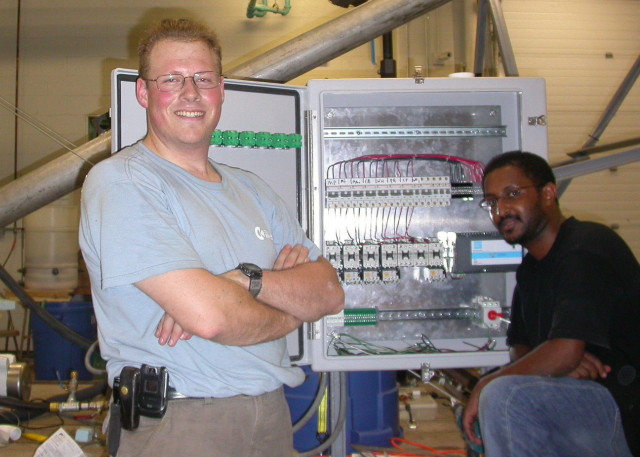 Here's Yotam and me in front of the enclosure before the conduit was installed and the wire was pulled. Yotam has also routinely proven himself to be equally capable with both tools and mathematics. He rewired a lot of motors, soldered lots of thermocouples, installed heater tape, and many other jobs, totally unrelated to his research in the area of system optimization.
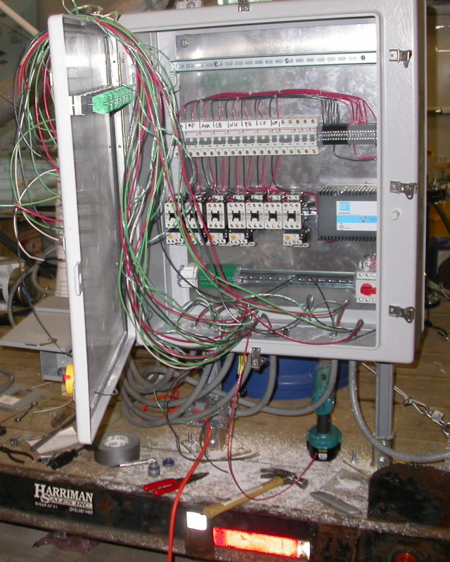 The electrical enclosure after pulling much of the wire. All wire is 12 GA. If we were to go with 120V, the wiring would have had to be 10 GA to carry the currents of the bigger pumps and the heater. All conduit is Sealtite brand, gas and liquid tight. Pulling through long lengths of this is a two man job, and it worked out best to stretch the conduit through its path, cut it, and then hold it straight while manning the fish tape. Wire could be pulled after the conduit was installed, but with all the bends it took more lubricant and muscle power than doing it straight.
 The finished electrical enclosure, after the hasty addition of a thermostat when it was proven that the water heater's internal thermostat was not accurate enough for this operation. The original idea was for a continually running heater pump, with the heating water temperature controlled by the thermostat in the water tank. This was replaced by a bang-bang heater, in which the water tank was set to it's maximum temperature and the heater pump cycled on and off under the control of the thermostat, which is sitting just below the contact blocks in the right side of the frame. Even with automatic control, the front panel switches all were designed to have "on/off/auto" settings, to allow for direct manual override. The top DIN rail was supposed to be for terminal strips to connect to the LV cabinet, which would have contained the PLC and other 24 V equipment to the contactors. This was never installed, and is part of the work for revision 2 of the digester.

