CraneController: Bringing Crane Machines to the 21st century
When I first moved to Colorado, I decided to pursue more opportunities in freelance engineering. One of the first contracts I picked up was to design a new controller board for what I have always called Magic Claw Machines. Turns out that Coast to Coast Entertainment was looking to get a new controller board designed for their Crane machines.
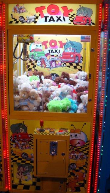 The standard Toy Taxi machine is shown. Coast to Coast shipped me
one of these machines, and the first thing I did was reverse engineer the
game's wiring harnesses, as the documentation provided was insufficient to design a
compatible board straightaway. I worked closely with Coast to Coast to get new features
out into the board, through sevral design revisions.
The standard Toy Taxi machine is shown. Coast to Coast shipped me
one of these machines, and the first thing I did was reverse engineer the
game's wiring harnesses, as the documentation provided was insufficient to design a
compatible board straightaway. I worked closely with Coast to Coast to get new features
out into the board, through sevral design revisions.
The controller developed for Coast to Coast is considerably more advanced than other crane controller boards on the market. It includes several neat features that are significant adders (or not available at all) on other machines. These features include:
- Interactive LCD Hand Control to set game options
- Web-interface available via wireless mesh network connection to monitor and configure machines
- Multiple play modes available, including play-until-win and various credit and claw strength settings
- Power up self test and LED indicators on PCB make troubleshooting easy
- Support for both software (via LCD control) and hardware (electromechanical) counters
- Customizable sound effects stored on SD Card
- Configurable for different game styles and chute locations
- Optically isolated inputs and outputs
- AutoClaw (tm) automatic claw strength setting simplifies changing out prize types
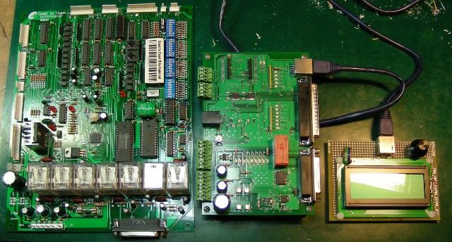 The original controller board is at left, and the original prototype version of the Stage 1 Controller is at right. The initial design had a lot of packaging differences that are still present in the production boards. NOtably, the form factor of the original protoype was set by a need to line up easily with existing screws and wirelengths inside the cabinet. The LCD module at right has since become a standard interface for me. It is a four-line LCD display with a rotary encoder for selecting options and scrolling through settings. The goal of this design was to make the game easy to configure, with intuitive menus. The LCD menu system has grown substantially since the initial design, and the production units now maintain various game counters, sound settings, networking options, and test features.
The original controller board has a single 25-pin connector for connection to the gantry, and then a large pile of 0.1" headers that are used to connect to to other game systems. The new board has the same gantry connector, but rather than all the 0.1" headers, it has a 37-pin D-Sub that mates natively to the in-game harness. This simplifies installation, and enables the board to be used in other cabinets by fabricating adapter cables that go from the 37-pin D-Sub pinout to whatever harness the game chassis requires. The 37-pin connector has bill and coin acceptor signals, toy detector in, and LED display output for the remaining credits, among other things. The concept originally was to use an integrated solid-state motor drive IC for driving the gantry motors, but variability in power supply output caused reliability issues. It was decided that a normal old-fashioned relay drive with snubbers would be more effective for this application.
 A close up view of the original prototype, with the Test Menu on the prototype LCD Hand Controller. The conectors along the top of the board are for the power supply inputs and programmer, as well as for an "aux" input / output set that was removed. The other goal we had to do for this was lots of diagnostic LED indicators, which I still use on current designs. It is great to have data read out on an LCD display module or computer interface, but it is also totally useful to have a light that goes on (or off) when something works (or doesn't). This board, and all future versions, have nearly two dozen indicator LEDs for various game status, the functions of which are all labeled on the board.
 This is the final version of the crane controller, which is currently available from Coast to Coast. At left is the 37 pin chassis harness connector. Above that, with the white RJ-45 cable attached, is the connector for the LCD Hand Controller. Immediatelly above the hand controller is the SD-Slot that stores the game's sound effects, which are changable by writing new files to the card. To the right of that is the wireless mesh module, then the bank of snubber-equipped relays for the gantry drive. At right is the DB25 pin connector for the gantry drive. The connectors along the bottom are for extra features not carrid on the DB37, including the chassis LED flasher lights, and various auxiliarly systems that are chassis-dependent. The same board is used in multiple types of machines. The RJ-11 connector at the bottom is for updating the board's firmware.
To save cost on manufacturing, as many components as possible are surface mount, and the board has components only on one side. Through-hole components were used when surface mount components were not electrically or physically appropriate or available, such as for the power relays, 0.1" headers, and D-style connectors.

