The Battery Spa @ SmartSpark Energy Systems
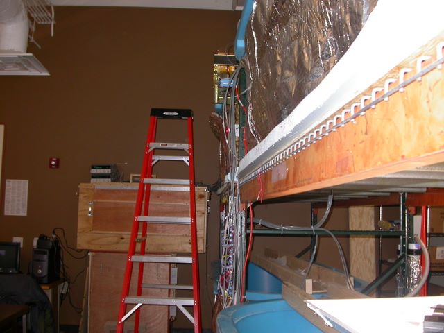 To the right is a side view of the four watertanks at SmartSpark Energy Systems.
In the distance is the HotBox described elsewhere on the web page, sitting atop another
hotbox that was built for another project. The tanks on the right are the subject here.
To give a sense of scale, the ladder is a standard 8-foot fiberglass ladder. The
original design goal for this system was to deep-cycle batteries under
controlled conditions while monitoring
the change in their capacities and properties. It was not possible to test
large strings of deep-cycle batteries in hotbox style enclosures, due to the
size required. We took a hint from other companies that test batteries, and instead
decided to use water immersion. I designed a system that consists of
four insulated 300 gallon horse troughs outfitted with spa equipment, insulation,
and a PLC to control charge and discharge. Other engineers at SmartSpark designed
the datalogging system for this.
To the right is a side view of the four watertanks at SmartSpark Energy Systems.
In the distance is the HotBox described elsewhere on the web page, sitting atop another
hotbox that was built for another project. The tanks on the right are the subject here.
To give a sense of scale, the ladder is a standard 8-foot fiberglass ladder. The
original design goal for this system was to deep-cycle batteries under
controlled conditions while monitoring
the change in their capacities and properties. It was not possible to test
large strings of deep-cycle batteries in hotbox style enclosures, due to the
size required. We took a hint from other companies that test batteries, and instead
decided to use water immersion. I designed a system that consists of
four insulated 300 gallon horse troughs outfitted with spa equipment, insulation,
and a PLC to control charge and discharge. Other engineers at SmartSpark designed
the datalogging system for this.
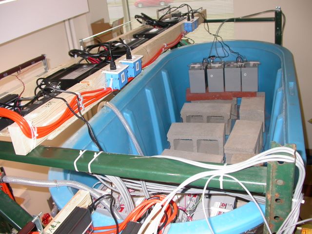 This is a view at the top tank, to illustrate the premise. In the distance are two 2x12
volt gel cell strings undergoing testing. The tanks are oversized for the application,
primarily to give thermal mass to the testing system. The batteries sit up on the bricks
to keep their terminals dry, while keeping a large volume of water in contact with
as much of the battery cases as possible. To the left is a wooden shelf containing
the chargers used for the batteries in this tank. There are some load resistors already
installed at the far left. The cable at right is for the datalogging system, and the
cables at left is all DC charge cable, control cable, or AC power cabling.
This is a view at the top tank, to illustrate the premise. In the distance are two 2x12
volt gel cell strings undergoing testing. The tanks are oversized for the application,
primarily to give thermal mass to the testing system. The batteries sit up on the bricks
to keep their terminals dry, while keeping a large volume of water in contact with
as much of the battery cases as possible. To the left is a wooden shelf containing
the chargers used for the batteries in this tank. There are some load resistors already
installed at the far left. The cable at right is for the datalogging system, and the
cables at left is all DC charge cable, control cable, or AC power cabling.
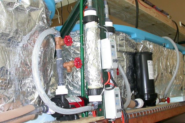 Shown here are two sets of spa equipment of the four total.
The tanks themselves were insulated, as
was as much of the plumbing as was practical. The water is sucked out of the tank
through a strainer in the bottom. It then enters a filter and the suction
inlet of the pump. From the pump the water flows through bypass and drain valves,
followed by the
heater element. Each tank was fitted with a 1.2kW resistive spa heater. They were
on sale at the spa parts warehouse and are actually higher wattage heaters
rated at 240 volts, running at a lower voltage. The water, after passing through
the heaters, goes out the tube at the top and back into the tank at the opposite end
of where it left.
Shown here are two sets of spa equipment of the four total.
The tanks themselves were insulated, as
was as much of the plumbing as was practical. The water is sucked out of the tank
through a strainer in the bottom. It then enters a filter and the suction
inlet of the pump. From the pump the water flows through bypass and drain valves,
followed by the
heater element. Each tank was fitted with a 1.2kW resistive spa heater. They were
on sale at the spa parts warehouse and are actually higher wattage heaters
rated at 240 volts, running at a lower voltage. The water, after passing through
the heaters, goes out the tube at the top and back into the tank at the opposite end
of where it left.
The plastic boxes are the typical Grainger thermostats used elsewhere with additional
switches added to make them double as junction boxes for the pump motor and heater
connections. The two switches are pump and heater on/off. All the AC
wiring in the system is GFCI.
One of the early problems our team had was with heat and water loss due to evaporation.
We were losing about 3 inches of water per day with the heaters running full tilt. To
address this situation, we ordered many pingpong balls and dropped them on the top
of the water. After that fix, evaporative water loss was down to 1/2" per day and
the heaters were running with a 30% duty cycle once the test temperature was reached.
Each morning, the first task I did was to check the water level. I rigged
up a manifold and some valves that run from the sink to each of the tubs, and installed
floating blocks tied to washers to read the water level without having to climb up a
ladder. Topping up the tanks each morning took about five minutes.
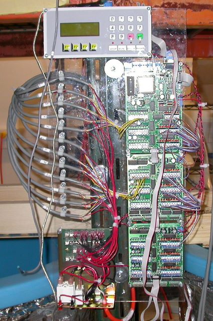 When thinking about the control, I wanted a system that was scalable, reliable,
affordable, and easy to start and stop. Due to the loads involved, we could have had
issues with our lab AC if too many chargers went into bulk mode simulataneously.
In order to prevent this, all 24 charge
circuits were connected to the PLC. The discharge cycles were initiated according
to the PLC's real time clock, and the charge cycles were started only when the
discharge cycle was completed and the PLC agreed to charge.
The LCD screen shows
the time, countdown to the next charge event, and number of cycles completed.
When thinking about the control, I wanted a system that was scalable, reliable,
affordable, and easy to start and stop. Due to the loads involved, we could have had
issues with our lab AC if too many chargers went into bulk mode simulataneously.
In order to prevent this, all 24 charge
circuits were connected to the PLC. The discharge cycles were initiated according
to the PLC's real time clock, and the charge cycles were started only when the
discharge cycle was completed and the PLC agreed to charge.
The LCD screen shows
the time, countdown to the next charge event, and number of cycles completed.
The PLC interfaced to charge boards, which were designed by another engineer at
SmartSpark. This board contained the relays to connect and disconnect
the chargers and loads, and the comparator to signal the PLC when the discharge
cycle was completed. One board was installed per two charge circuits.
One of the valid lessons learned from this project was that if there is already
something out there that does the job, it will probably be cheaper and easier
than doing it yourself. When deciding on the control circuit for this, there
was some interest in whipping out VHDL and writing up a "simple" program,
assembling a PCB, and on and on. This definitely would have worked, but why bother?
SmartSpark wasn't then in the business of building industrial controls. This PLC cost
something like $1200 for the whole setup, which is undoubtedly cheaper
than the engineering time, debugging time, etc of the VHDL solution. The company
even fixed one of the boards for free when I explained a problem!
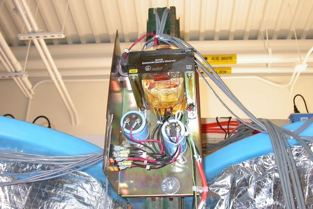 The bottom of the PLC board contains the power distribution board, which takes 24
volts DC from this big linear surplus supply, puts it through breakers, and sends
it out to the relay boards. Originally the power distribution board was attached to
this big linear supply, where that jagged metal end is on the left of the frame. This
thing weighs a heafty 40 lbs or so, but for about $1.00 per pound for 20 amps of
almost 24 volts, it's quite a bargain compared to other options. Out of frame,
but directly below this is a large "emergency stop" button.
It's big, and red, and quite obvious.
Thankfully we never had to use this, but when pressed, it would interrupt the power
to all the control circuits, which would open all the relays and disconnect the batteries
from the chargers or loads. The E-stop ended up being more like the power switch for
the system.
The bottom of the PLC board contains the power distribution board, which takes 24
volts DC from this big linear surplus supply, puts it through breakers, and sends
it out to the relay boards. Originally the power distribution board was attached to
this big linear supply, where that jagged metal end is on the left of the frame. This
thing weighs a heafty 40 lbs or so, but for about $1.00 per pound for 20 amps of
almost 24 volts, it's quite a bargain compared to other options. Out of frame,
but directly below this is a large "emergency stop" button.
It's big, and red, and quite obvious.
Thankfully we never had to use this, but when pressed, it would interrupt the power
to all the control circuits, which would open all the relays and disconnect the batteries
from the chargers or loads. The E-stop ended up being more like the power switch for
the system.
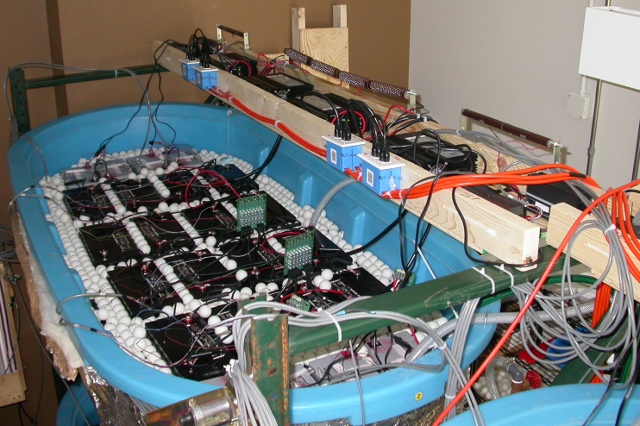 Lo, the batteries in their lovely watery goodness. In the tank you can
see the floating pingpong balls, keeping the water from evaporating.
This tank contains four strings of 4x sealed batteries, plus 4x additional
strings of 2x sealed batteries, all with different types of equalization
equipment. The wooden shelf over the top holds the load resistors, battery
chargers, and charge switching boards, which were controlled by the PLC
described earlier.
Lo, the batteries in their lovely watery goodness. In the tank you can
see the floating pingpong balls, keeping the water from evaporating.
This tank contains four strings of 4x sealed batteries, plus 4x additional
strings of 2x sealed batteries, all with different types of equalization
equipment. The wooden shelf over the top holds the load resistors, battery
chargers, and charge switching boards, which were controlled by the PLC
described earlier.

